The WiiBook is a project to take the motherboard of an old unibody Macbook Pro (made in 2009-2012), and transplant it into the shell of a Wii. Since these old laptops had CD drives inside of them, this constrained the motherboard to a very specific footprint, which almost exactly matches that of the Wii's motherboard, making this swap possible. All of the materials for the project can be found at this Github page, and the instructions are below.
An early image of the WiiBook.
Motherboard installation
The first step is to empty out the Wii's case, so that there are no internal components remaining other than the LED board for the disc drive. Follow this guide for help on this process.
Next, use a Dremel to cut away the back panel of the Wii, using the power supply and USB ports as guides for the width of the cutout, as well as removing any standoffs on the bottom shell of the Wii. At this stage, print the "macbook-io-shield" and "magsafe-brace" files and ansure that they will fit alongside each other in the removed section of the back panel. Once this is done, glue down the thinner piece from the printed IO shield, aligning it with the left-hand side of the back panel.
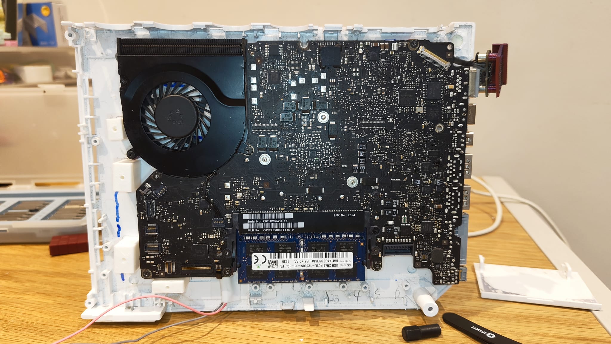
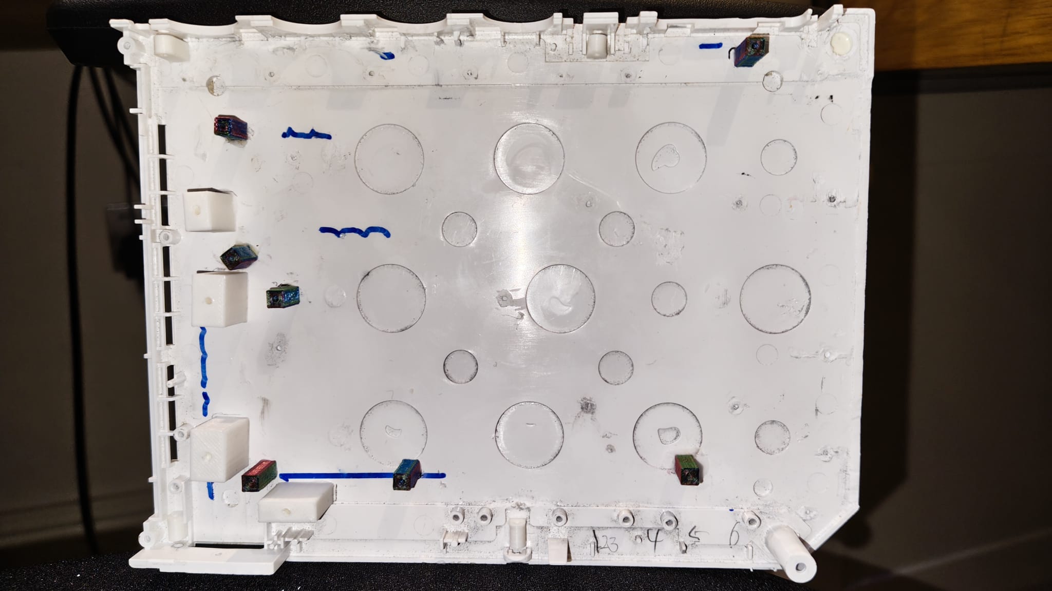
After this, disassemble your Macbook to remove the logic board (follow this guide for help) and fan, then attach the standoffs from the "case-standoffs", "standoff-9mm", "standoff-12mm", and "standoff-13mm" files to the motherboard of the Macbook. The 9mm standoffs attach to the motherboard's fan, the 13mm standoffs attach to the two screwholes in the bottom-right, and the rest of the standoffs are 12mm. The case standoffs should be attached onto the bottom case where the retention screws would attach the top case to the bottom case: each hole is at a different height. Use the below image as a reference for the standoff placement, and then glue each of the standoffs to the bottom of the Wii shell.
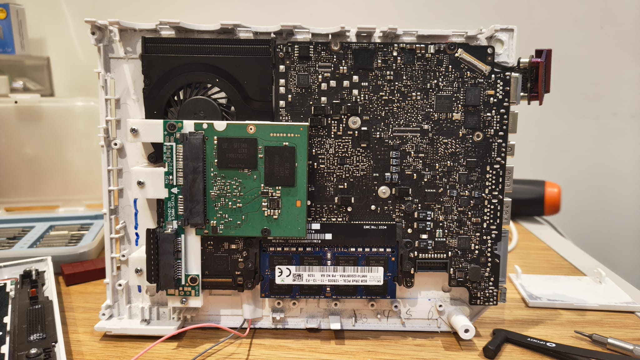
At this stage, the Macbook motherboard can be screwed into the base of the Wii and left there, using a Dremel to remove any pieces of plastic on the bottom case which interfere with the Mac's placement. The next step is to remove the enclosure of both the CD drive converter and your SATA SSD, to isolate the PCB for the hard drive and the SATA cable adapter inside the drive converter. Plug the SSD into the correct side of the SATA adapter, screw this assembly into the "ssd-adapter-bridge" print, and then attach each of the "ssd-standoffs" to this assembly. This should work with any CD adapter and SSD, but you will have to amend the SSD adapter bridge to have the right screw locations if you use different products to those linked in the BOM.
Take the CD drive cable from the Macbook and plug it into the SATA adapter and motherboard (it should fold under the adapter bridge safely). Mark the location of the SSD standoffs, unscrew these standoffs and detach the SSD assembly, then glue the SSD standoffs to the bottom of the case and reattach the SSD.
LED ring assembly
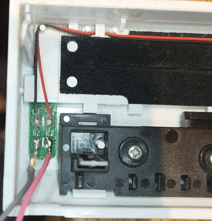
Remove the keyboard backlight flex cable from the Macbook (you can cut this off rather than extracting the entire flex cable). Use a knife or a soldering iron to remove the top layer of plastic and expose the copper routing underneath this wrap. Take the Wii's front cover, find where the LED wires meet a small PCB, and desolder the wires here which go to the Wii's motherboard. Solder new wires about 10-15cm long to the now-empty pads, as below:
Now, solder the other ends of these wires to the Macbook's backlight cable. The black/grey wire connects to the left-hand side of the cable, with the red connecting to the right-hand side of the cable as it plugs into the Macbook. It is recommended to use electrical tape or anything similar to attach the end of this cable close to the motherboard, so that it does not have tension on it during the assembly process.
At this point, the Wii should look like this:
Exterior work
Next, take the "magsafe-brace" print and screw the Magsafe port to this assembly. Glue the bottom of this piece to the Wii's case to sit flush with the rest of the Macbook's IO. You may need to remove some plastic from the corner of the Wii's shell with a Dremel so that this piece fits. Then, take the second half of the "macbook-io-shield" print, gluing it to the top half of the Wii shell to fit with the Macbook's ports.
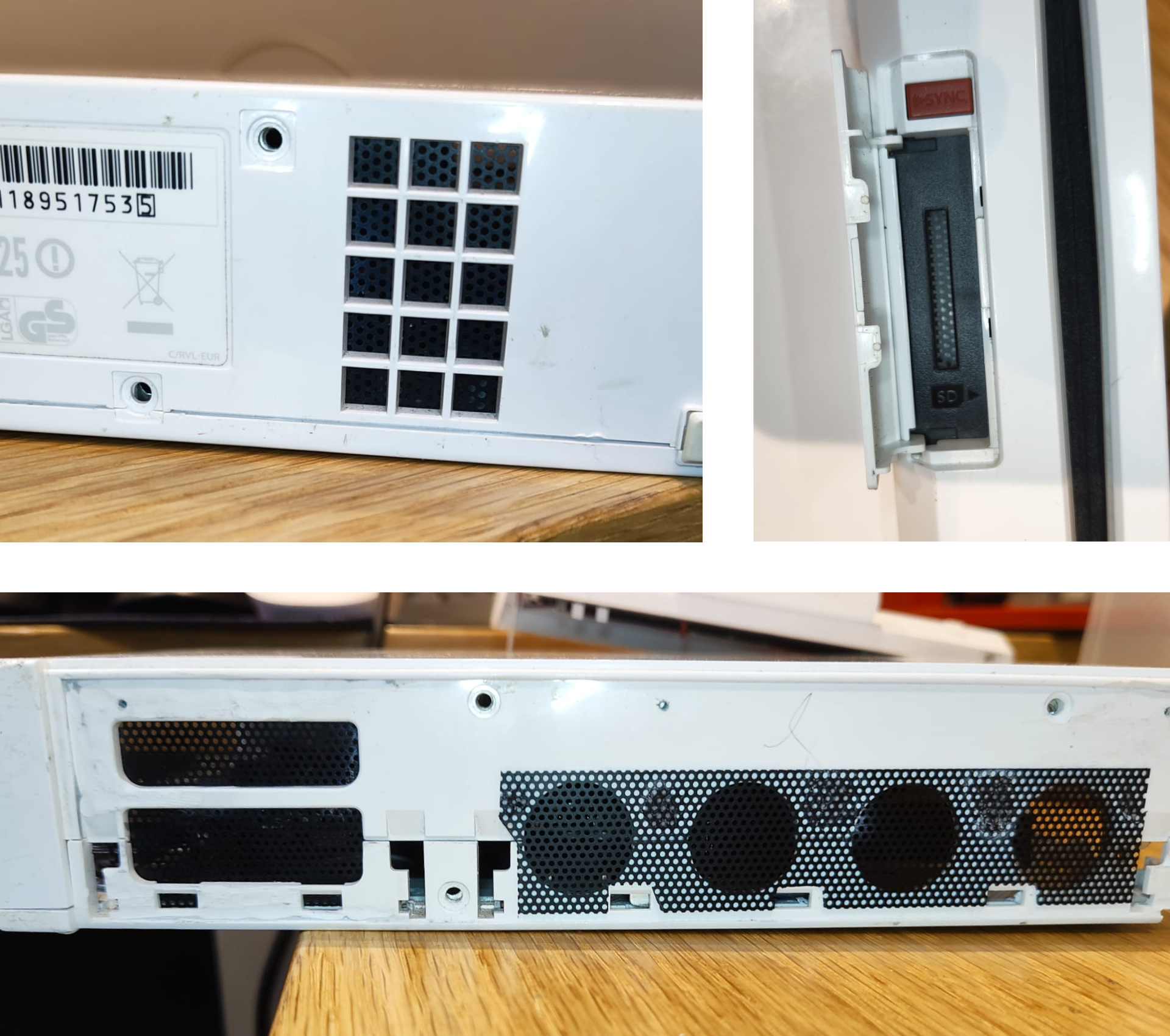
Finally, take the fan mesh, and cut out four rectangles to fit the Wii's shell cutouts for the Gamecube controller ports, memory card ports, SD card slot, and original airflow intake. Glue the fan mesh to the inside of the Wii shell - except for the controller ports, which should be glued on the outside, to the top half of the shell - as below:
At this point, the only thing left to do is to assemble the Wii back together, and the project is complete!